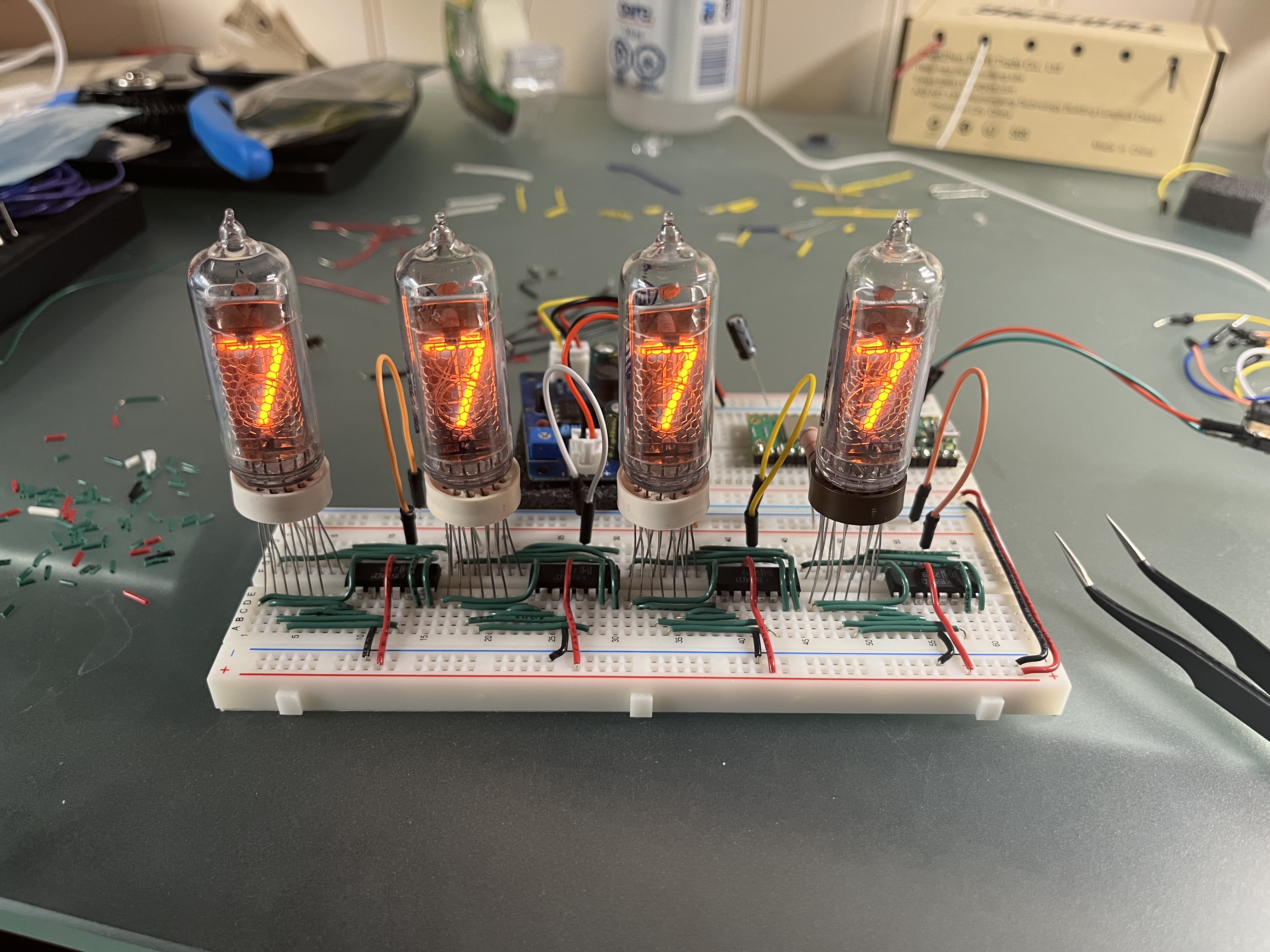
The finished product with a counting program
Introduction
If there's any display technology that instantly screams "retro", it's the nixie tube. It has a 'steampunk' feel or maybe some kind of 'retro-modernism'. It'll probably surprise you then, that they were invented in the 1950's.
Fun fact: nixie tubes are shown in Oppenheimer even though it took place more than 10 years before they were invented!
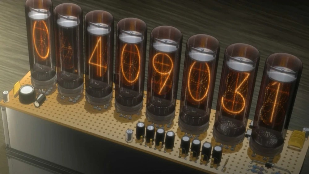
This is definitely an unpopular opinion, but I actually like the aesthetic of breadboard projects. They have a 'prototype-y' style. My primary inspiration was the divergence meter from Stein's Gate.
He uses a protoboard here which is certainly cleaner, but I find the solder connections on the bottom are harder to keep neat.
Build log
Parts list
- IN-14 nixie tubes. These are classic tubes which can be distinguished with the upside-down '2' used for the 5.
- K155ID1 nixie tube drivers.
- Raspberry Pi Pico W. The W version allows for wifi access which means you can use it to display any number you want on the fly.
- Solid core wires. I used 22 gauge.
- Breadboards. I used a full size and a half size.
- High-voltage DC power supply (~170V). The nixie tubes take a lot of voltage to run. Always be cautious when working with high voltages.
- 5V voltage regulator
- DC input jack
- 12V AC to DC adaptor
- Standard resistors and capacitors. I used 4x10kΩ resistors, 4x0.1uF capacitors, 1x1uF capacitor.
Circuit
I referenced GreatScott's guide. Unfortunately, the schematic has a few wiring inconsistencies between the nixie tubes and driver. I'll upload a corrected one when I get a chance. Make sure to consult the datasheets for the right connections.
Step-by-step
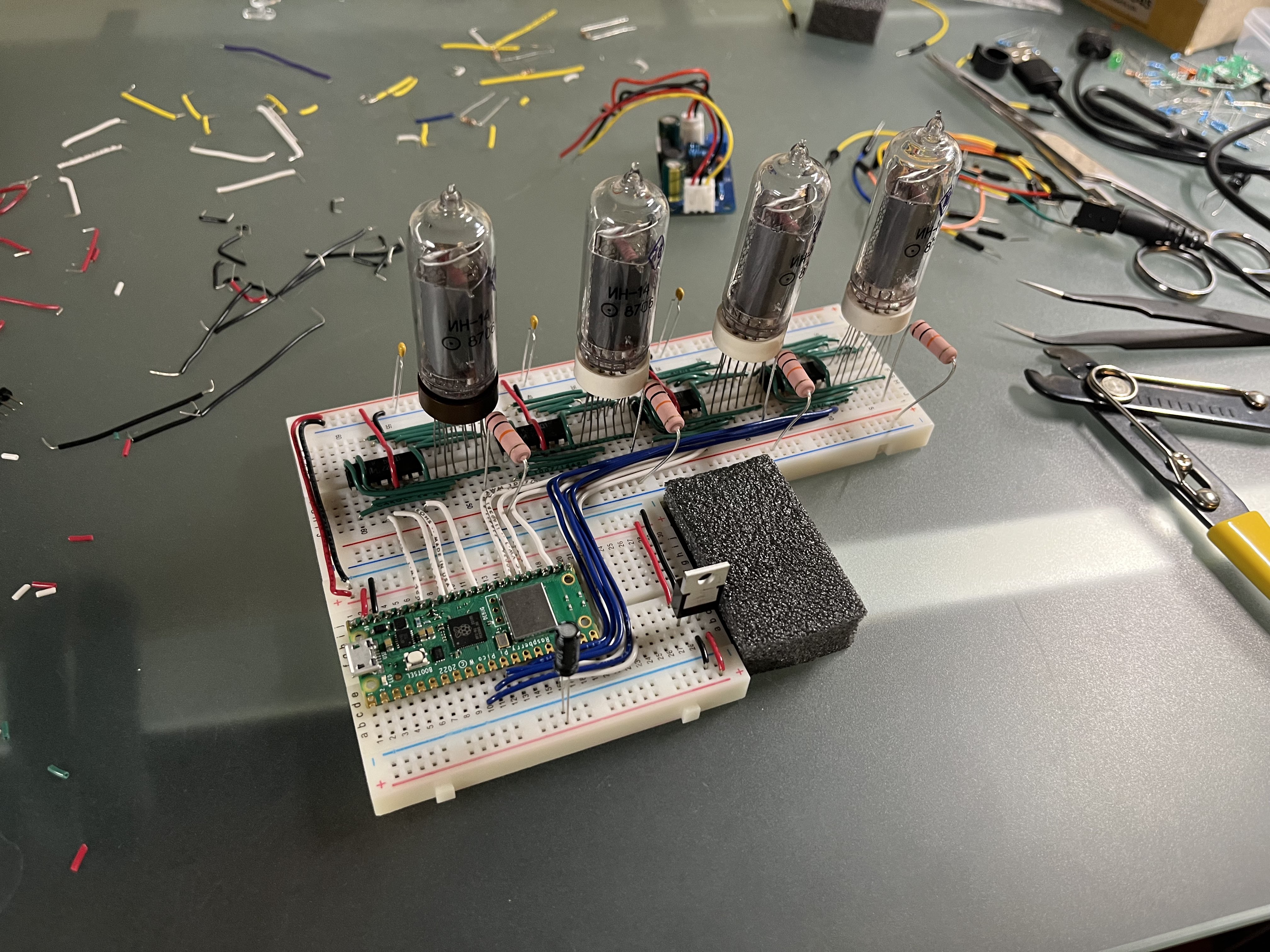
I started with putting the breadboards together and planning the circuit. The Pico takes up the half-size breadboard and the tubes/drivers will be on the full-size breadboard. Each tube takes 7 rows and each driver takes 8 rows. For 4 tubes and 4 drivers, that's 60 pins in total - just enough to fit!
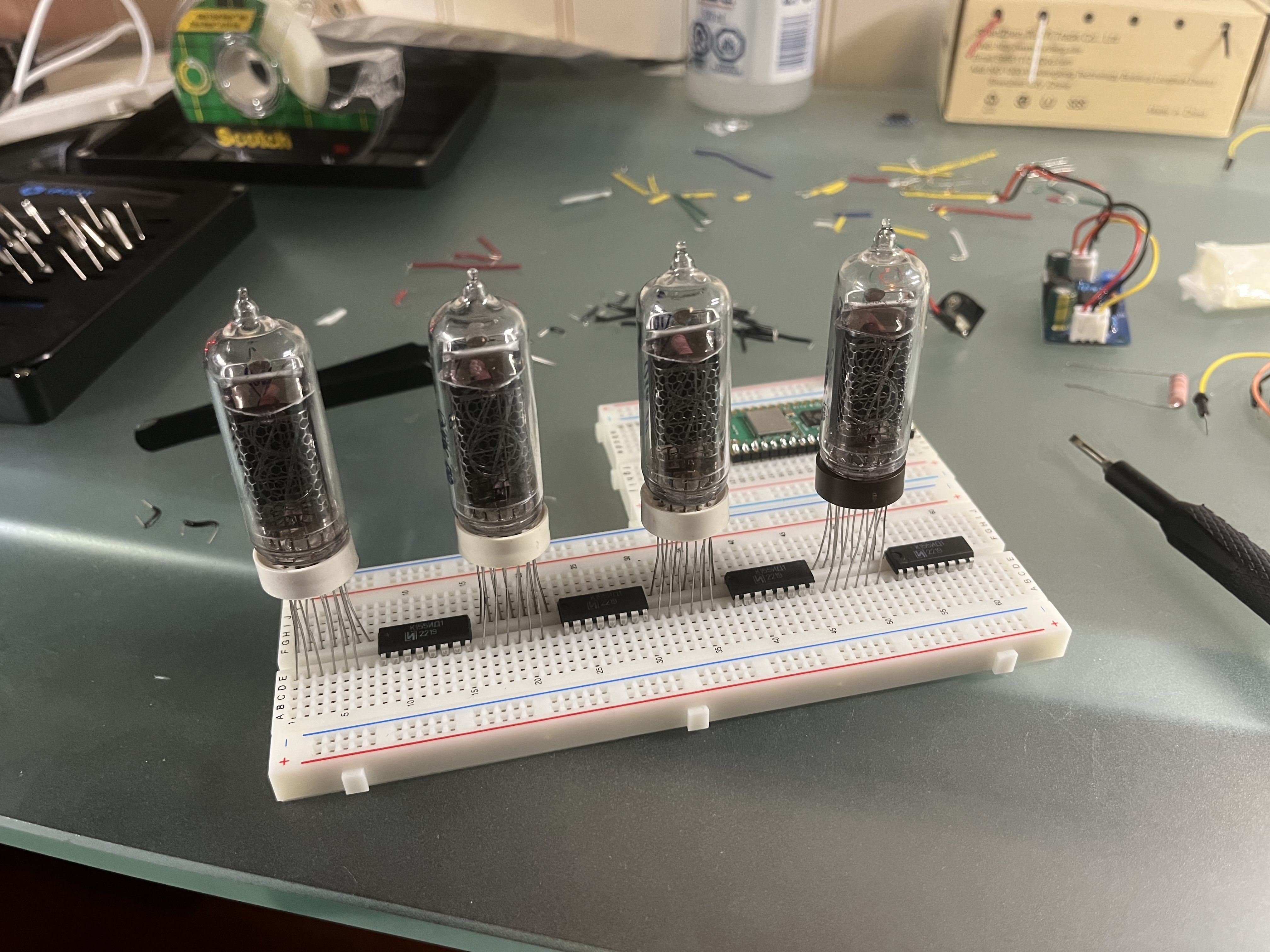
Next, I wired up the first tube to its driver. I used solid core wire and cut each connection depending on the length needed. It's a time taking process, but well-worth it if you want a neat breadboard.
So, why not use jumpers? Jumpers are awesome for prototyping, but for something more permanent, solid core is reliable and keeps the whole circuit flat and neat.
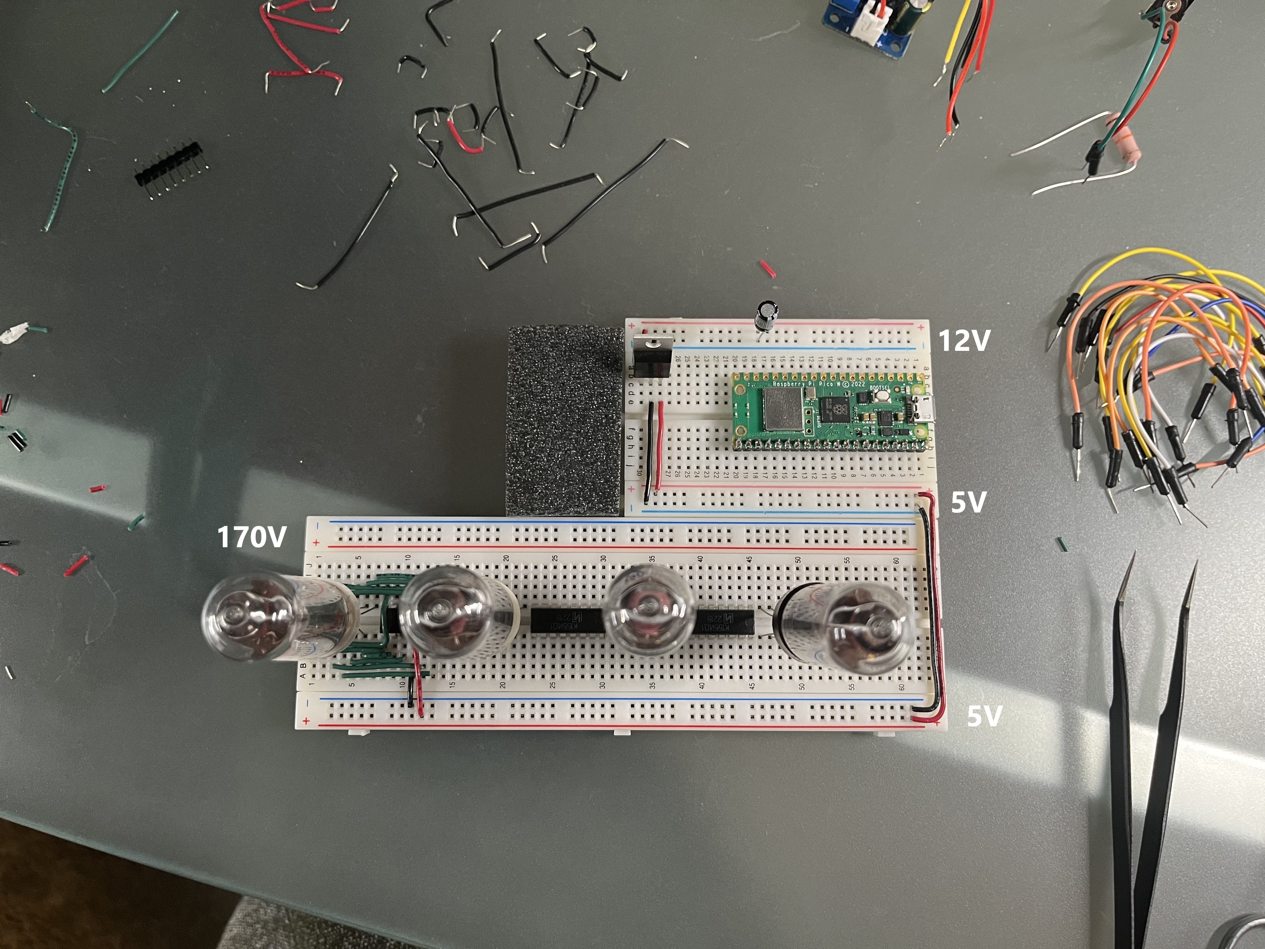
The input from the wall adapter (12V) goes into the top rail of the half-size. The high-voltage power supply will take 12V and convert it into 170V in the top rail of the full-size. The voltage regulator sends 5V in the bottom rail of both breadboards. 5V is used for the Pico and drivers.
Let's plug in 12V power and the 170V power supply. I connected a 10k resistor from the 170V rail to the tube (it's hidden behind). Since the driver needs a valid input to allow the current through, I connected pin D on the driver to ground to test the circuit.
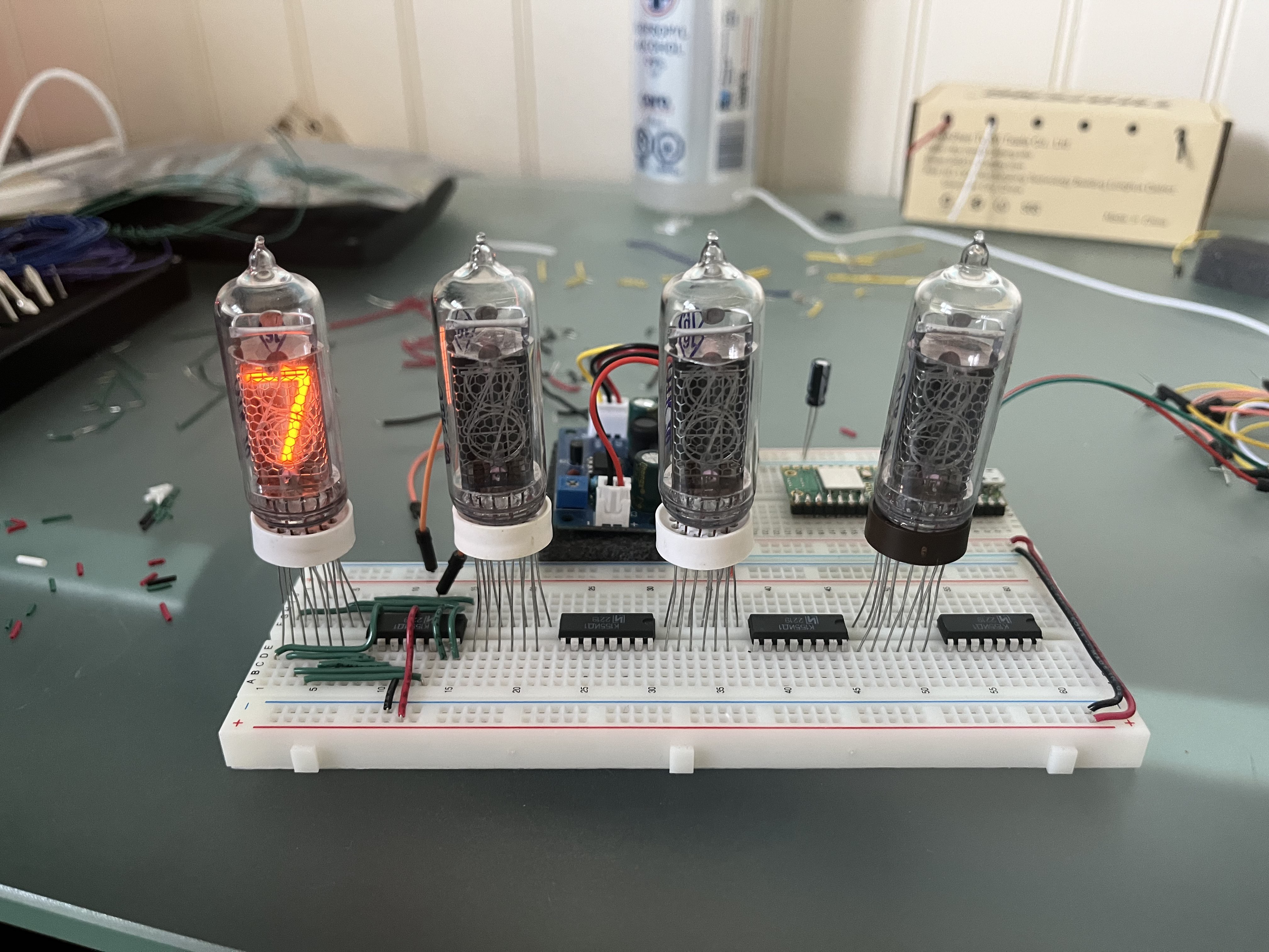
Looking good! I then repeated the same wiring for the next 3 tubes.
Now, wire up the input pins on the drivers to the Pico. Make sure to connect them to GPIO pins. You can find a pinout diagram in the documentation.
Let's program the Pico and we're done!
Programming
I recommend MicroPython for the Pico W. There is a C/C++ SDK for the Pico, but it is not easy to make HTTP requests. Generally, MicroPython is simpler if speed isn't a big deal for you. You'll have to flash the Pico with the MicroPython image and from there, you can use Thonny to upload programs easily.
Set up your pin list. Use the GPIO numbers, not the physical pin numbers.
PIN_LIST = [
    # A   B   C   D  (GPIO pin numbers)
    [28, 26, 22, 27],   # 1's
    [20, 18, 17, 19],   # 10's
    [15, 13, 12, 14],   # 100's
    [10,  8,  7,  9],   # 1000's
]
Use a helper function to turn this into actual pins.
def pin_list_to_pins(pin_list):
    for i in range(len(pin_list)):
        for j in range(len(pin_list[i])):
            pin_list[i][j] = Pin(pin_list[i][j], Pin.OUT)
Now, we can create some functions to set each digit individually, and as a whole.
# Sets the given pins to the 1's digit of value.
# pins - [A, B, C, D]
# value - 0 to 9
def set_digit(pins, value):
    pins[0].value(value % 2)
    value //= 2
    pins[1].value(value % 2)
    value //= 2
    pins[2].value(value % 2)
    value //= 2
    pins[3].value(value % 2)


# Sets the given pins to len(pins_list) digits of value.
# pins - [ [A, B, C, D], ... ]
# value - integer
def set_number(pins_list, value):
    for digit in pins_list:
        set_digit(digit, value % 10)
        value //= 10
Let's add a timer to create a simple counting program.
timer = Timer()

count = 0

def countup_callback(t):
    global count
    set_number(PIN_LIST, count)
    if count >= 9999:
        count = 0
    else:
        count += 1

timer.init(freq=10, mode=Timer.PERIODIC, callback=countup_callback)
Getting data from the web
Conclusion
This looks so cool. I'll probably set it to show the minutes that have passed since my last League game haha. I highly recommend this project if you aren't scared of higher voltages. Thanks for reading!