I made a video documenting the full build process + typing sounds. Check it out on Youtube!
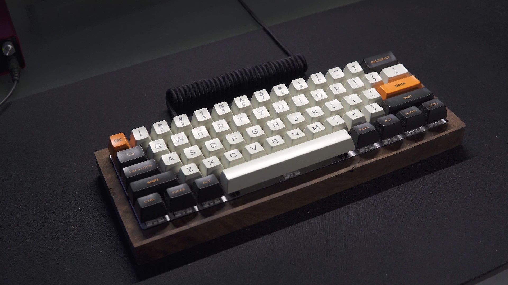
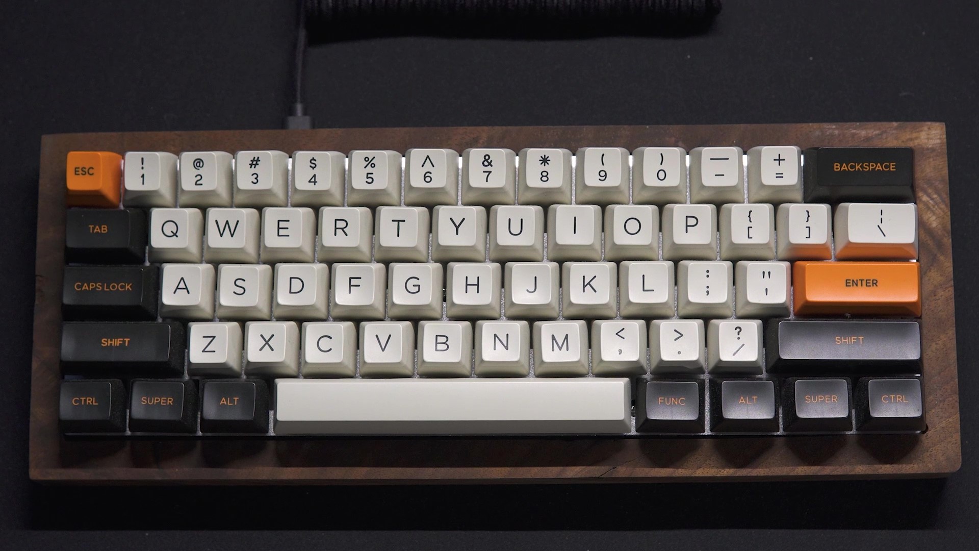
The final product
Introduction
This project has been with me basically all throughout high-school and the two years of University. I started with buying up parts in late Grade 9 and put together a crappy version that looked pretty bad and half the keys didn't work. My tech teacher called my work "not the work of an electrician". He was absolutely right and I spent a while machining the case, rewiring, and trying my hardest to get it to work (it didn't).
Come University and I finally decided to make it work once and for all. I took everything apart and rebuilt it from scratch, keeping only the plate from my high-school version. Here's how I did it.
Build log
I used matt3o's fantastic guide. My build steps are fairly similar with a few modifications for my specific purpose.
Parts list
- Kailh box white switches
- gh60-style aluminum plate
- Domikey carbon SA keycaps
- Krytox 205 g0 lube
- Teensy 3.2
- 1N4148 diodes
- USB breakout board
- Solder and soldering iron
- Wires and ribbon cable
Step-by-step
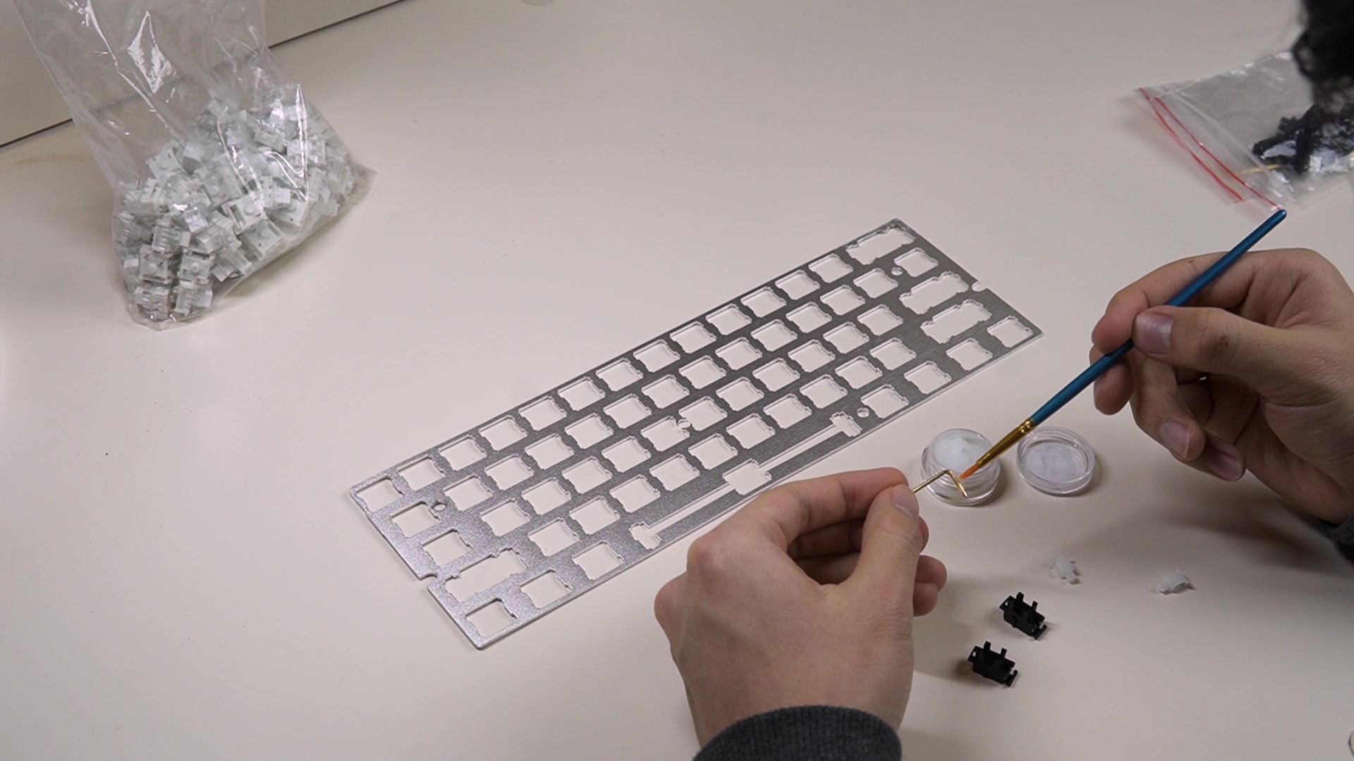
Lubing
The stabilizers keeps wide keys like SHIFT, SPACE, ENTER to go down evenly even if you press down on the edge. I lubed the stabilizers with Krytox 205 g0 so that the movement is smooth is not scratchy. Usually people will lube the switches as well (here's a video where I did that), but since these switches are clicky, we skip that step.
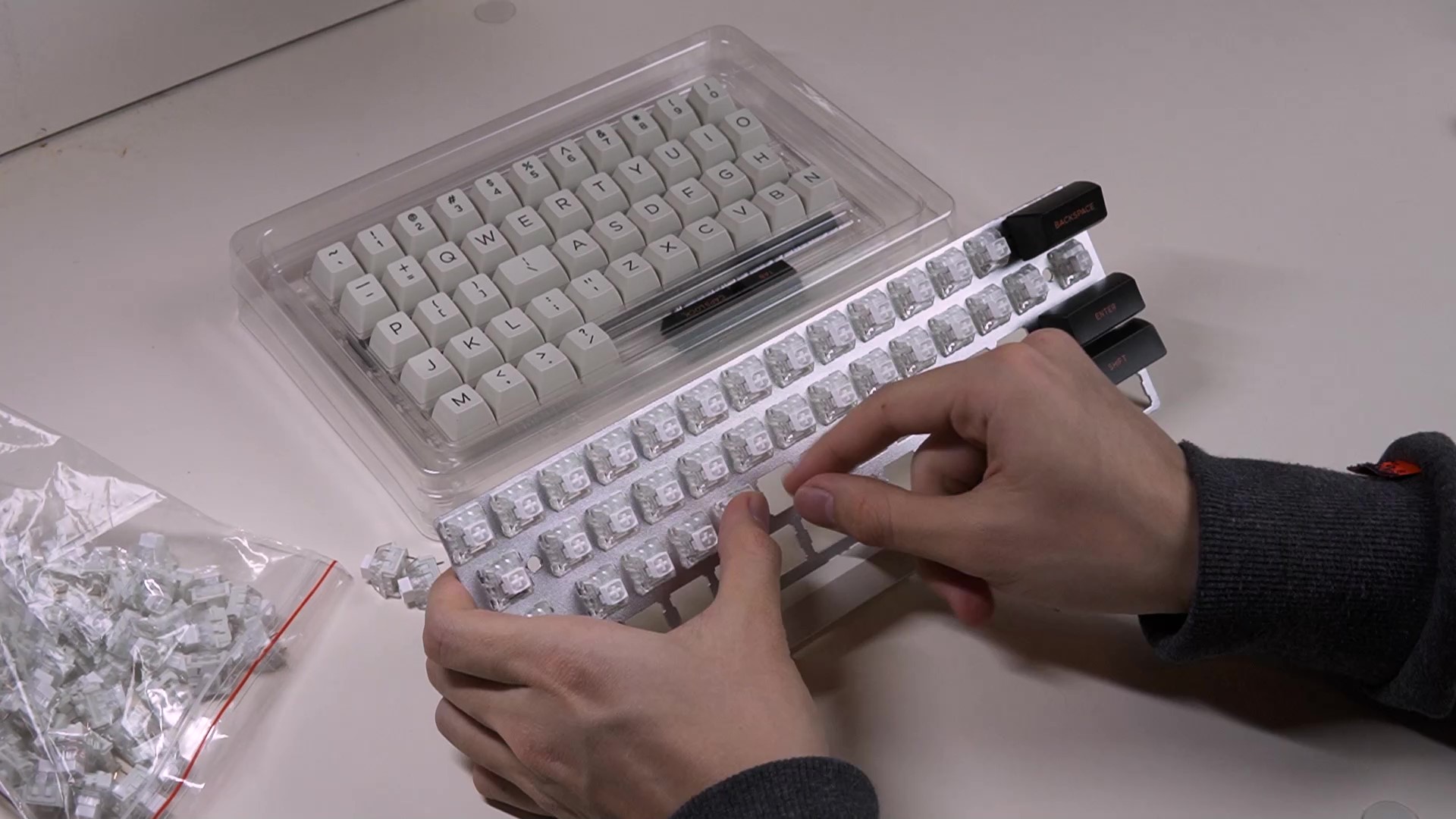
Switches
I'm using Kailh Box Whites which are clicky switches. These are mid-tier switches, but I really like the clarity of their sound and the cost isn't too bad either. I put in all the switches first because they have to be in place for when we create the wire matrix on the back.
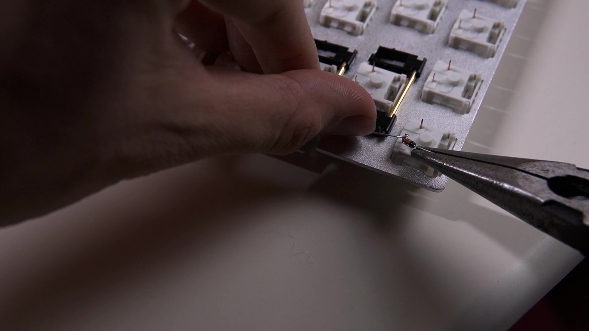
Diodes
I made the loop directly around the pin instead of pre-making the loop. I pulled the loop as tight as possible and added solder to the loop until just before the shape became round instead of conical. Make sure the black end is in the right direction.
Rows and Columns
I used the Capri Tools wire stripper to strip in the middle of wires. I put the wire along the row and marked the spots on the wire where diode legs were. Then, I stripped the wire, made a strong half loop with the diode, and soldered.
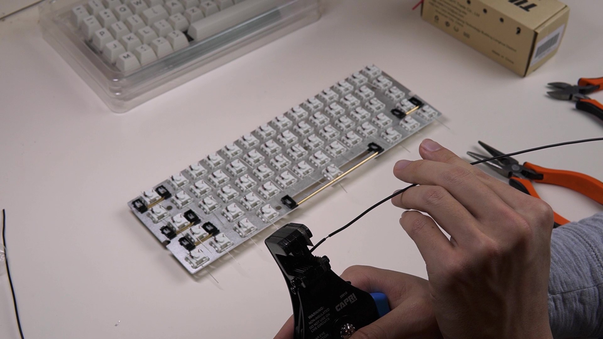
I did something similar with the columns, but instead of wrapping the diode leg around the wire, I wrapped the wire around the pin.
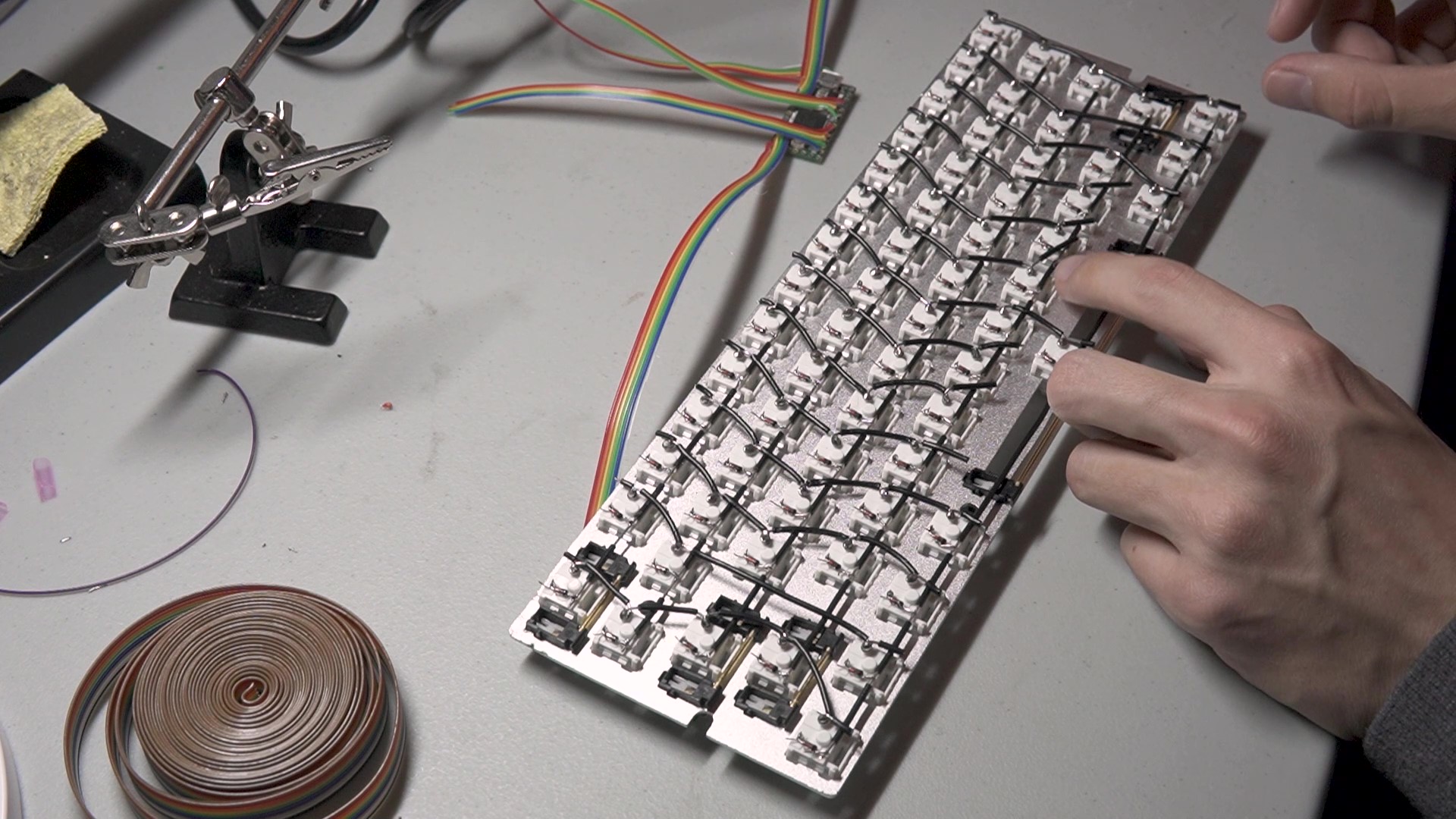
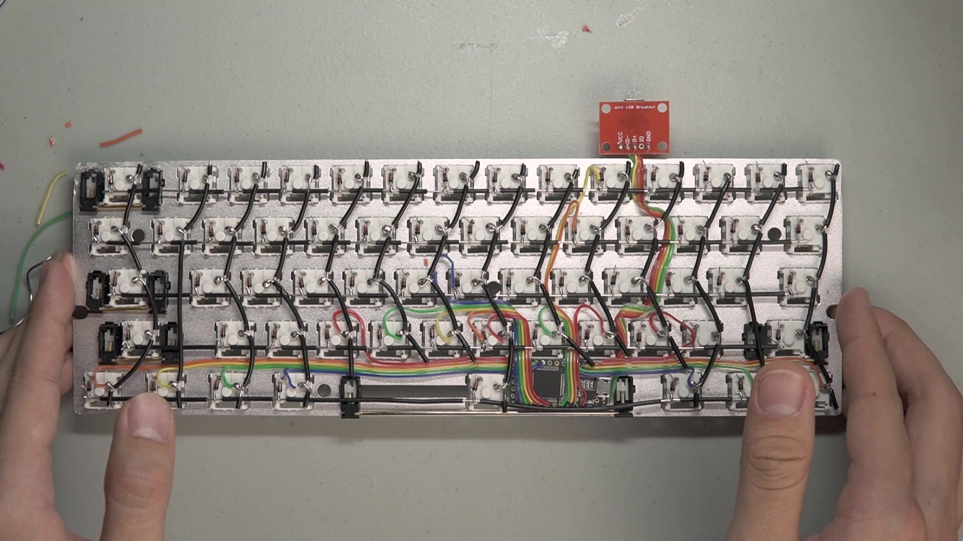
Microcontroller
I used the Teensy 3.2 microcontroller and wired up ribbon cables. You'll need one wire for each row and one wire for each column. Note: to avoid routing a thick USB cable through the matrix, I connected ribbon cable to the USB contacts on the bottom of the board. Check the "Pin Assignments, Back Side" section for the 3.2 here.
Keycaps and case
I put in Carbon SA (clone) keycaps and put it into a wooden case I made. My case is simply a wooden box. For those who would like to try this at home, I recommend that you machine the case with a little inset for the edges of the plate to rest on. This keeps the keyboard stable and lessens the work for matching standoffs and screws.
Programming
QMK Firmware is open-source and well supported. Since my plate is a GH60, I configured my layout to match it. Then, I was able to use the QMK Configurator to get the exact layout I wanted.
Also, make sure these pins match correctly with your wiring. Here's what mine turned out to be:
#define MATRIX_COL_PINS { B17, A12, A13, B16, C2, D5, B3, B0, C0, C7, D3, C3, C4, C6 }
#define MATRIX_ROW_PINS { D6, C1, D1, B1, D0 }
Conclusion
This is time consuming. But, if you stick with it and care about the details, it can be very rewarding :)